This isn’t much more than an “I made a thing” post. You have been warned.
I’m sure many of you are familiar with the iconic British sitcom “The IT Crowd”. There are so many memorable quotes and gags, but my favourite has always been “The Internet” from the series 3 episode “The Speech”. I liked the episode so much that I decided to build my own replica of the little black box.
The box was the hardest part to find. I recognised is as a Maplin project box, but Maplin are long gone from the high street, and the online incarnation don’t seem to sell them. Thankfully I never throw anything out, and I had one in a box in my garage that I bought years ago. The next step was to build a circuit that could sit inside the box – hence my renewed interest in the astable multivibrator circuit.
The PCB
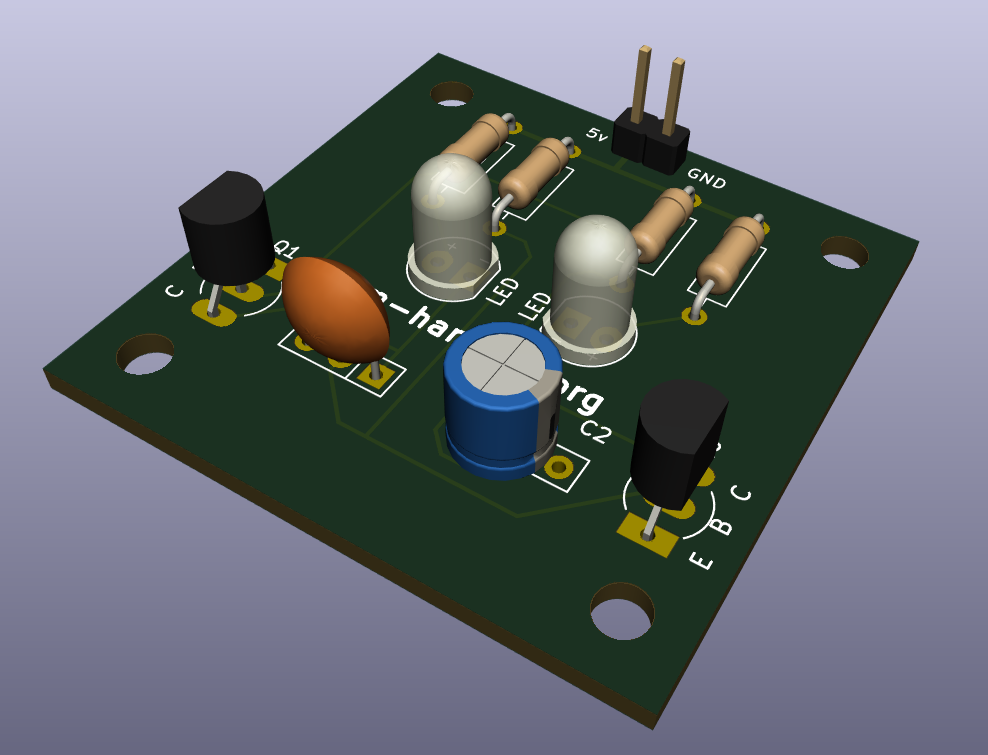
The circuit board inside the box was designed in Kicad. It measures 40mm x 40mm so is small enough to fit into many different project boxes and enclosures. I added M3 mounting holes to the corners, though in the end I didn’t end up using them when mounting the board inside the project box.
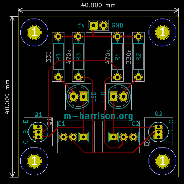
The component footprints are not included on the silkscreen. Ordinarily it is a good idea to include them if you have the space, but because I wanted to be able to select different component values for different flashing rates I left them on the fabrication layer. Having them already there means that should I decide to make a board where fixed values are required I can switch them back to the silkscreen layer easily.
The transistor, LED and capacitor component footprints are all customised. I wasn’t sure what transistor I’d end up using so instead of using one of the standard TO-92 footprints I created one that showed which pin should go where. This is useful because while some transistors like the 2n2222 are manufactured so that pin 1 is the emitter, pin 2 is the base and pin 3 is the collector, others such as the BC547 have the collector and emitter reversed. The pin pitch of the footprint is 1.27mm, so transistors can be soldered flush with the board. This is aesthetically pleasing, but can be difficult to solder.
The capacitor footprint has 3 pins, so that parts with a 2.5mm or 5mm pin pitch can be used. This was for my convenience, because most of the electrolytic caps I have have a 2.5mm pitch, but the multilayer ceramic caps I have all have a 5mm pitch, and I wanted to avoid bending the leads as much as possible.
The LED footprint is based on a standard footprint, but I added polarity markings so that if pin headers were used instead of soldering the LED directly to the board it would be easy to see which way round to plug the connector in.
To get the board to work with only one LED the second LED footprint must be shorted with a link. It is a good idea to use a higher value resistor between the voltage rail and the positive side of the shorted LED pad. This will limit the current through the transistor so that when the LED is off less current is being shorted to ground.
I used the following component values to achieve the short flash followed by a long pause:
| Component | Value |
|---|---|
| R1 | 330 Ω |
| R2 | 470 kΩ |
| R3 | 1 MΩ |
| R4 | 47 kΩ |
| C1 | 1 μF |
| C2 | 10 μF |
Lessons learned
This was a fun little project, and it feels good to get back to using KiCad again. Making my own component footprints was interesting, and I’m proud of how this board turned out.
The only change I would make if I was to have a second batch made would be to change the TO-92 footprints to ones with a pitch of 2.54mm. The transistors end up sitting higher on the board so they aren’t as aesthetically pleasing, but they are much easier to solder. I did design an alternative version of the board in Kicad, but I haven’t bothered to get it manufactured.
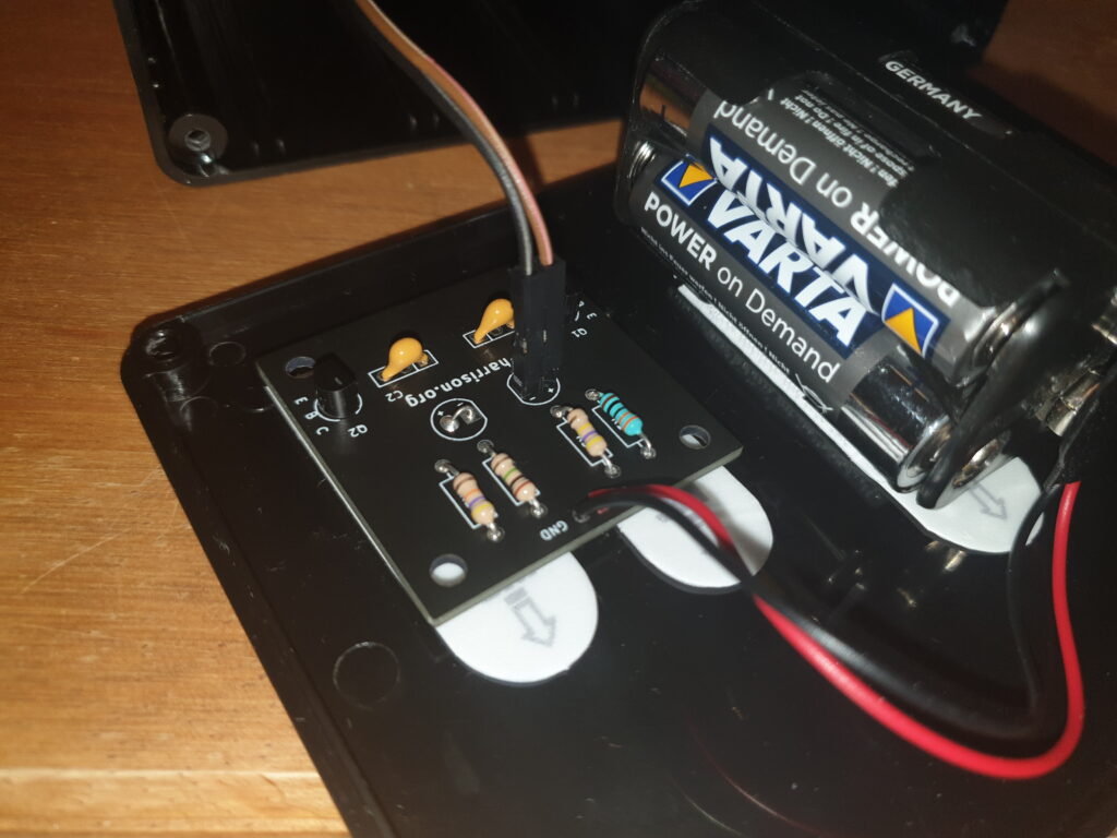
I was going to use stand-offs to mount the board inside the box, but I didn’t have any plastic ones that I could glue to the bottom plate. Instead I used double-sided tape strips. It’s not ideal, but I didn’t want to screw through the bottom of the box.
Downloads
If you want your own astable multivibrator PCB I’ve included download links below for the Kicad project and gerber files for both versions of the board.
Leave a Reply