This is my first Arduino example sketch – hopefully the first of many.
This sketch allows you to control a 7 segment LED display using an Arduino and a 4094 shift register. Only 4 data pins are used on the Arduino, rather than 8 if you were to control the 7 segment display directly. For this example I used a common cathode LED display.
Simply copy the code below into the Arduino IDE, build the circuit explained in the notes and watch the numbers count up.
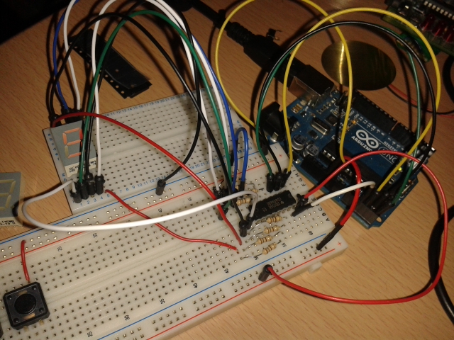
/*
Demonstration of the use of a 4094 SIPO shift register to control a 7 segment display by Matt Harrison
Adapted from the example found at http://arduino.cc/en/Reference/shiftOut

Connect the 4094 to the Arduino as follows:

* Strobe pin (pin 1) to A3
* Data pin (pin 2) to A4
* Clock pin (pin 3) to A5
* Output Enable pin (pin 15) to A2

7 Segment Display connections
(via a 180-220 ohm resistor for each connection):

4094          7-Segment Display

Q1 (pin 4)    a
Q2 (pin 5)    b
Q3 (pin 6)    c
Q4 (pin 7)    d
Q5 (pin 14)   e
Q6 (pin 13)   f
Q7 (pin 12)   g
Q8 (pin 11)   h

Other 4094 connections:

Pin 8 to ground
Pin 16 to 5v (or 3.3v if applicable)

*/

//Pin connected to Strobe (pin 1) of 4094
int strobePin = A3;
//Pin connected to Data (pin 2) of 4094
int dataPin = A4;
//Pin connected to Clock (pin 3) of 4094
int clockPin = A5;
//Pin connected to OE (pin 15) of 4094
int oePin = A2;

/* Decimal representation of binary numbers for each
digit in the 7 segment display from 0 to 9

*/
byte segChar[] = {63, 6, 91, 79, 102, 109, 125, 7, 127, 111};

void setup() {
  //set pins to output because they are addressed in the main loop
  pinMode(strobePin, OUTPUT);
  pinMode(clockPin, OUTPUT);
  pinMode(dataPin, OUTPUT);
  pinMode(oePin, OUTPUT);
  digitalWrite(oePin, HIGH);
}

void loop() {
  //count up routine
  for (int i = 0; i < 10; i++) {
    //set strobe pin low to begin storing bits
    digitalWrite(strobePin, LOW);
    shiftOut(dataPin, clockPin, MSBFIRST, segChar[i]);
    //set strobe pin high to stop storing bits
    digitalWrite(strobePin, HIGH);
    delay(500);
  }
}
There are a few of things to consider when adapting this code. First, the strobe pin must be set low before using the shiftOut function, and must be set high after the data has been sent. Secondly, you can set the output enable pin high or low at any time to switch the display on or off. This can be used to only activate the screen when it has something to display, or to blink the display on or off.
The segChar array contains the decimal equivalents of the binary numbers for each character on the 7 segment display, form 0 to 9. segment A is the least significant bit (LSB) and segment B is the most significant bit (MSB). As an example, to represent the character “1” segments B and C must be lit, so the binary number 00000110 is sent to the shift register. The array contains the numbers in order, and they are indexed by their intended display value, from 0 to 9. You can change the values in the array to represent any character that is displayable on a 7 segment display, but be sure to make a note of the characters you are representing and the order in which they are stored in the array.
Leave a Reply